
 We fell in love with Griffin Wayne’s 1972 Mist Green Chevy Blazer the minute we saw it. I mean, who wouldn’t. It’s classic 4×4 iron, and Wayne had done it up just the way we would if we owned it. Gorgeous paint, just enough suspension lift to get 35-inch rubber underneath, heavy duty axles with beefy differentials and the right gearing, a crossover steering conversion, and a 383ci stroker V8 that kicked out plenty of power.
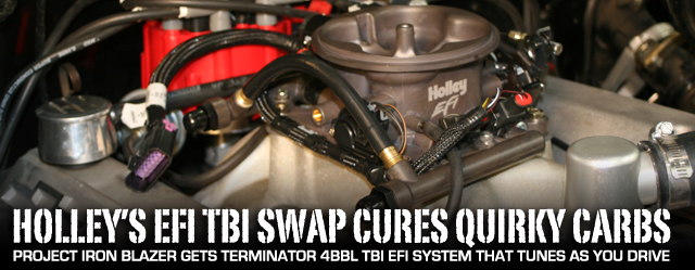
It ran pretty good, but every once in a while, the carburetor would act up when the K5 was climbing very steep off-road terrain, or working it’s way through off-camber challenges. Aside from that, Wayne was looking for a little edge when it came to overall drivability, improved cold starts, and better low- and mid-range acceleration.
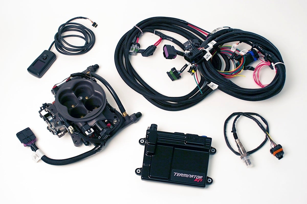
The Holley Terminator EFI 4BBL TBI kit comes with the throttle body unit, ECU, oxygen sensor, hand-held controller, main EFI wiring harness, power harness, and the brackets and hardware necessary for installation.
These are a few of the advantages offered by the new Holley Terminator EFI 4 BBL Throttle Body Injection System. It’s available in a Polished Aluminum or Hard Core Gray finish model, we chose the Hard Core Gray for the installation. Among its other key benefits and features is a fully self-tuning ECU, no laptop required. It self-tunes after proper installation as you begin to run the engine and drive the vehicle, delivering the required air/fuel mixture for optimal economy and power.

The heart of the Holley Terminator EFI system is a 4BBL 950 CFM throttle body unit that supports 250 to 600 HP engines.
The 950 CFM throttle body features Holley’s patent-pending annular discharge fuel ring for maximum flow and fuel atomization. The 80 pound/hour-flow rate injectors support engines ranging from 250 to 600 HP.
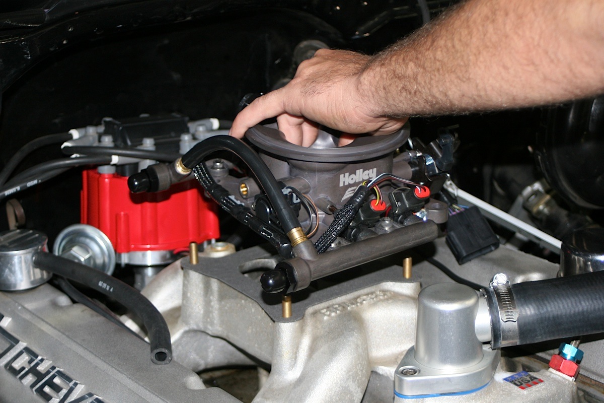
Its sensors are integrated into the throttle body and pre-wired for simple one-click assembly. And the unit is designed to work with Ford, GM TH350 and 700R4, as well as other transmission linkages; and will fit on any 4150-style square-flanged intake. As Blane Burnett, Marketing Coordinator for Holley said, “It’s easy due to our TBI unit’s basic design; it simply replaces the carb atop the intake manifold and bolts right on.”
The Holley Terminator EFI TBI unit also provides ignition timing control on engines with Small Cap HEI and Ford TFI distributors (requires an adapter). The Terminator ECU can be updated to Holley “HP” ECU specs with free downloadable software, and then the ECU can be used for LSX, boosted, nitrous, and many other applications.
Best of all–Holley offers free tech support. We have detailed the entire installation step-by-step for you in this article; and then for a brief re-cap, we have a six-minute video near the end of the article.
What You’ll Need First
When spec’ing out your kit with Holley, be specific about your vehicle, model and its components, as there will be certain optional parts needed for the installation depending upon the vehicle. Regardless of what you have, prior to installation, you will need a fuel system and return fuel lines. A complete high pressure EFI fuel system must be installed for the Terminator.
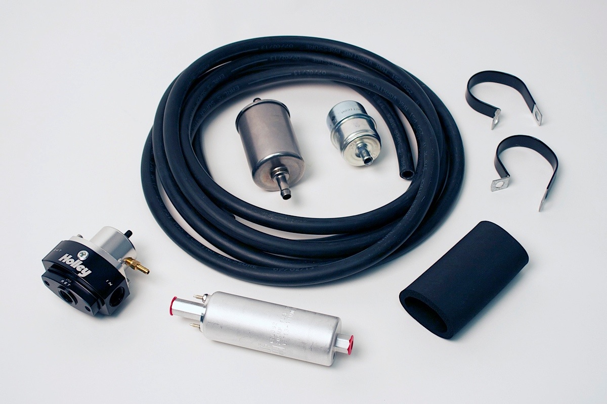
We chose Holley fuel kit No. 526-4. It offered everything needed for the Terminator EFI system, including No. 12-920 in-line fuel pump, a billet regulator, two metal filters, barbed hose ends and Earl’s Super Stock hose.
The pump needs to be capable of 255 liters/hour or 400 pounds/hour of fuel at 45 PSI. When using an in-line fuel pump, a coarse pre-filter must come before the pump and a 10 micron post filter after the fuel pump. An EFI fuel pressure regulator is required, and should be installed after the throttle body.
Burnett told us that to make things easy for Holley customers, “We made sure to release several fuel kits ranging from budget conscious push lock rubber hose all the way up to our Earl’s stainless steel braided kit with AN fittings and billet inline pumps and regulators.”
Holley offers four fuel system kits. These kits contain all components except the return line. A fuel gauge capable of reading up to 100 PSI will also be needed to check for proper fuel pressure. It requires a 1/8-inch NPT port for installation (Holley fuel pressure regulators have a 1/8-inch NPT port).
In addition to the above list, the engine must be equipped with a four barrel intake manifold. Any square-flange, Holley 4150 type intake manifold will work. A spread bore intake manifold may work with no adapter as long as it is an aftermarket “universal flange” (meaning it has dual bolt patterns).
The manifold flange must also have enough material so that no vacuum leaks occur along the perimeter of the throttle body. If there is not enough material, a sealing plate (Weiand No. 9006) can be used. Factory dual plane intakes require an adapter (Holley No. 17-6).
Removal Of Existing Components
First things first–for safety’s sake, we disconnected the battery. Then to get at the carb, we removed the air cleaner. But don’t toss it, as this will fit nicely and work just fine on top the Holley EFI TBI.
Before we disconnected any vacuum hoses, we thought it might be a good idea to sketch out the vacuum hose routing. You may want to do the same. Using masking tape and a marker, you can number all the vacuum hoses, sources, ports before removing the old fuel delivery system.
The fuel line that connects the carburetor to the mechanical fuel pump can be thrown away, as it will not be needed for the installation. However, keep the throttle return springs for later installation. Remove the carburetor, and at this time, if required, replace the intake manifold.
While cleaning existing manifold, place clean shop towels or rags into the manifold opening to prevent dirt or debris from entering the engine. Dirt or debris could get into the engine, cause damage, and possibly necessitate a complete engine overhaul.
Remove all traces of the old gasket material from the intake manifold mounting flange. Take care to not gouge the intake manifold sealing surface during removal of old gasket material, but failure to remove all traces of old gasket material will result in vacuum leaks. Sealing flanges must be clean and dry before installation of the Terminator EFI TBI.
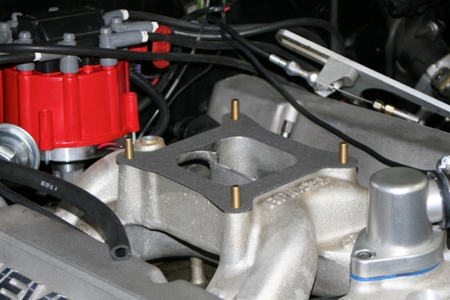
Remove the carburetor, and at this time, if required, replace the intake manifold. The engine must be equipped with a four barrel intake manifold. Any square-flange, Holley type intake manifold will work. Install the four manifold flange studs into the intake manifold. Place the throttle body gasket on top of the manifold flange surface.
Installation Of The Terminator EFI TBI
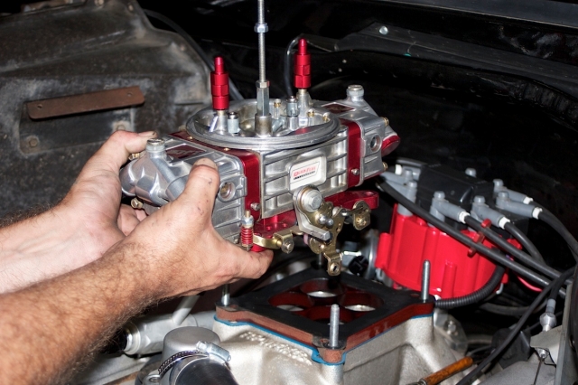
Install the four manifold flange studs into the intake manifold. Place the throttle body gasket on top of the manifold flange surface, and then place the throttle body in position over the manifold flange studs with the throttle lever located on the driver’s side. Be sure there is sufficient thread engagement of the throttle body hold-down studs and nuts.
It is very important that you check for proper clearance now between engine components, such as the distributor, coil, etc., and the Holley EFI throttle body. Also check for clearance between air cleaner and the closed engine hood at this time. If any problems are encountered, make corrections now.
Place the throttle body on the manifold with the throttle lever located on the driver’s side. Be sure there is sufficient clearance between all other engine components to ensure proper and safe operation.
Tighten the throttle body down progressively in a criss-cross pattern to between 5 and 7 foot-pounds to prevent leaks and avoid causing damage to the throttle body. Over tightening the TBI manifold flange hold-down-nuts can result in a warped or cracked throttle body.
Connecting The Throttle Body
It’s easy due to our TBI unit’s basic design; it simply replaces the carb atop the intake manifold and bolts right on. – Blane Burnett, marketing coordinator, Holley

The Terminator’s throttle lever is designed to connect directly to most throttle cables, and several throttle studs are included in the kit. It’s also designed to directly connect up to GM transmissions including TH350, TH200R, and TH700R4. A stud is included for most of these transmissions.
Wayne’s ’72 Blazer was equipped with a TH350, so that made this job that much easier. We installed the proper throttle and transmission studs, and secured them with two of the included lock washers and 1⁄4-28 nuts.
There are two throttle cable brackets that come with the kit: one for engines with no transmission cable (it has a lower profile); the other is for engines that have a transmission kick down cable. Since the Blazer had a TH350 tranny, the cable bracket for engines with no kick down cable was used. Once installed, the 1⁄4-20 x 5/8 SHCS and a lock washer was used to secure the cable.
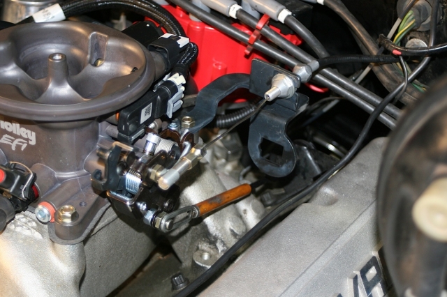
The Terminator's throttle lever is designed to connect directly to most throttle cables, and several throttle studs are included in the kit. We installed the proper throttle and transmission studs, and the external throttle return springs removed from the carburetor. These should be used in addition to the springs on the throttle body itself. The vacuum lines that were disconnected during removal of existing components were also connected to the Terminator EFI TBI at this point.
We installed the external throttle return springs removed from the carburetor. These should be used in addition to the springs on the throttle body itself. With the throttle linkage connected, we got in the vehicle and worked it back and forth a few times to make sure the action was smooth, and to get the adjustment just right so the throttle plates are vertical when the throttle control is wide open.
This is important because a sticky throttle could mean loss of engine or vehicle control. On Chrysler vehicles, a lever extension (Holley No. 20-7) will be needed. Van applications may require the use of throttle lever extension Holley No. 20-14.
The vacuum lines that were disconnected during removal of existing components were also connected to the Terminator EFI TBI at this point. These are the full manifold vacuum ports and the single timed spark (vacuum advance) port.
Coolant Temperature Sensor Installation
The coolant temperature sensor must be installed in a coolant passage in either the intake manifold or cylinder head. The sensor has 3/8-inch NPT threads. If only a 1⁄2 -inch NPT port is available, an adapter will have to be used. It is best to drain some of the coolant before the sensor is installed.
Do not install the sensor in the thermostat housing, or in an area that will not see a constant flow of coolant. We installed it in a pre-existing 1/2-inch NPT port in the 383’s intake manifold near the cylinder head.
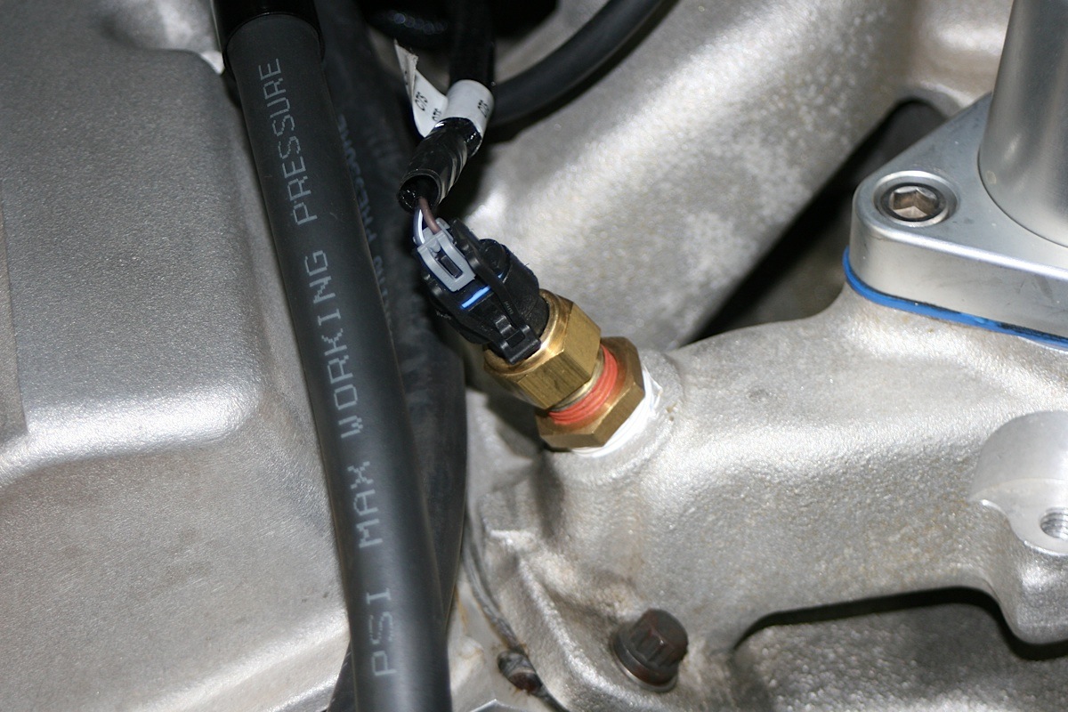
We installed the coolant temperature sensor at a pre-existing location in the intake manifold near the cylinder head.
Oxygen Sensor Installation
The oxygen sensor needs to be mounted where a good average of all the cylinders on one bank can be read–somewhere slightly after all the cylinders merge. Do NOT mount the sensor far back in the exhaust. This will negatively impact closed loop operation response.
It should be approximately 1 to 10 inches after the collector if you using long tube headers, and at least 18 to 24 inches of exhaust pipe must be in place after the sensor. If your vehicle is running a catalytic converter, the sensor must be located between the engine and the converter.
Our ECU and the oxygen sensor work together and learn faster than other competing systems. – Blane Burnett
The installation instructions provide a diagram showing how the oxygen sensor should be mounted in the upper half of the exhaust tubing, at an angle greater than 10 degrees from horizontal so that condensation in the exhaust tubing will not enter the sensor. The sensor can be mounted on either side of the exhaust tubing.
We found an appropriate location forward of the Y-collector pipe and drilled the recommended 7/8-inch hole. Then the threaded boss was welded into the hole. We made sure to weld all the way around the boss to crate a leak-proof connection, and then installed the oxygen sensor into the threaded boss securely. It’s a good idea to add anti-seize to the threads to aid in removal; but don’t get any anti-seize on the tip of the sensor.

The oxygen sensor should be mounted in either side of the upper half of the exhaust tubing, at an angle greater than 10 degrees from horizontal to keep condensation from entering the sensor.
Fuel System Installation
At this time we also did the plumbing job on the fuel system. The inline fuel pump, filter, 10-micron post filter were installed on a small protective platform, a skid plate you might call it, that was fabricated from sheet metal and then attached to the skid plate that protects the Blazer’s stock fuel tank. The sheet metal platform sits in front of the fuel tank, supporting and protecting these three valuable components as they do the job of pumping and filtering fuel on its way to the Holley Terminator EFI TBI.
The stock fuel pump on the engine block was removed and the mount/intake was closed off using a block-off plate since it was no longer needed. A bypass fuel pressure regulator was installed in the return line between the Terminator EFI TBI and the tank. In this case, we used the existing hard fuel line for a return line to the tank–waste not, want not–and plumbed it to one of two vent locations in the top of the tank.
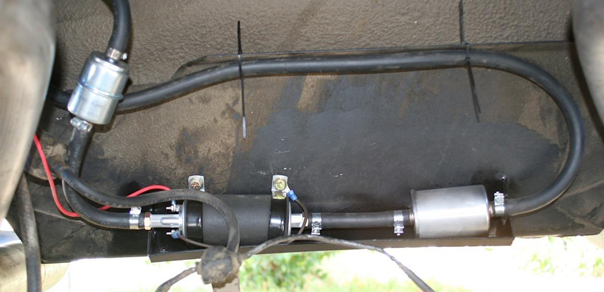
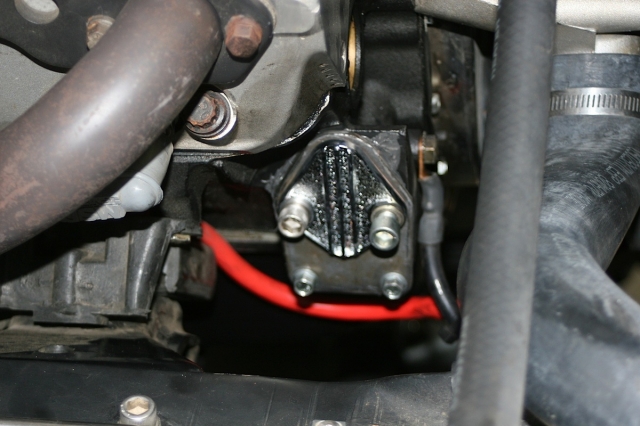
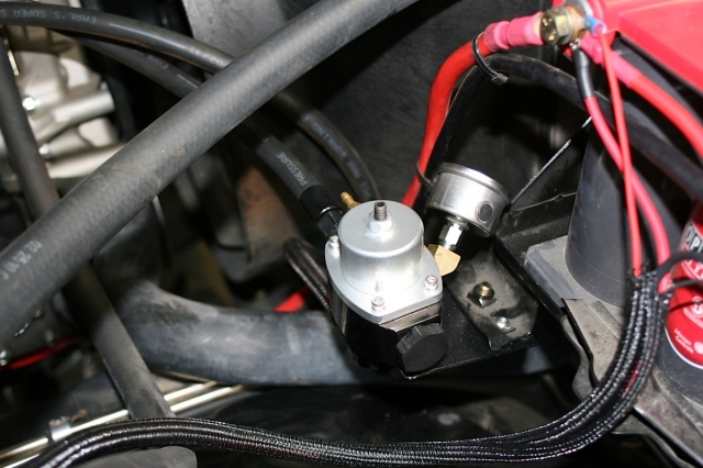
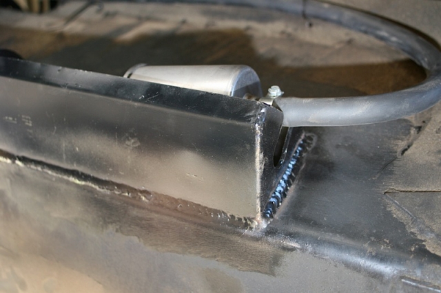
The inline fuel pump, filter, and 10-micron post filter were installed on a small platform (top photo) fabricated from sheet metal welded to the skid plate that protects the Blazer's fuel tank. The stock fuel pump on the engine block was removed and the mount/intake was closed off using a block-off plate (lower left) since it was no longer needed. A bypass fuel pressure regulator and transducer (lower center) was installed in the return line between the Terminator EFI TBI and the tank. A close-up (lower right) of one end of the shelf/skid-plate for the fuel filter pump system.
ECU Mounting
The ECU can be mounted inside the passenger compartment (preferable location) or in the engine compartment. If you do decide to place it in the engine compartment, it should be located where it won’t come in to contact with water or road debris, and away from the heat of exhaust manifolds or headers, as well as spark plug wires, CD ignition boxes, or other electrical devices. Also be sure the ECU is mounted so that the connecter end is pointed down so water can’t enter the ECU terminals.
The ECU comes with mounting hardware (stainless steel screws and nuts) and plastic shoulders on the mounting ears. We mounted the ECU on the center of the firewall inside the K5 just underneath the dash. Take care to not over-tighten the mounting hardware if you mount the ECU on a curved surface, as you can crack the mounting tabs or the housing of the ECU.
Wiring Harness Installation
The next step was to begin threading the wiring harnesses and hooking up the various sensors and the new components we had installed on Wayne’s ’72 Blazer. The main harness is the one that supports all the engine sensors, fuel and ignition. There are two main connectors for this harness that plug into the ECU.
The ECU has two main connectors. The first connector next to the USB connector is the “P1A” connector (34 pin). This connector is primarily an “Input” connector. It contains all the sensor inputs and wide band oxygen sensor control. The second connector is the “P1B” connector (26 pin). This connector is the “output” connector. It has 8 injector outputs and outputs for other devices.

The ECU was mounted inside on the firewall to keep it safe from heat, water and debris, yet still easily accessible.
If the ECU is mounted in the interior, the harness will have to be routed through the firewall into the engine compartment. Use a 2-inch hole saw to create a hole in a desired location if no other point of access is available. A grommet is supplied for a 2-inch hole to seal this area. We were able to find a passageway and did not need to cut a hole for the harness.
If the ECU is mounted in the engine compartment, the hand-held tuning module cable will have to be routed to the “CAN” connector on the main harness (located near the ECU connector main connector). This is assuming you want to access the hand-held module after startup. This also will require routing the small CAN connector somewhere through the firewall.
Connect the P1A and P1B connectors of the main harness into the ECU. About 18 inches from the ECU main connectors is a 40A relay that powers the injectors and fuel pump. There is also a 20 amp fuse for the injectors and fuel pump pre-installed in this location.
Each connector on the main harness is labeled with the sensor names, making assembly very easy. If you need an extension cable for the oxygen sensor, one is available from Holley (No. 534-199).
A fuel pressure transducer connector is also pre-installed in the main harness. The system is plug-and-play configured for a Holley 100 PSI pressure transducer (No 554-102). If these are not connected to a pressure transducer, the pressure will read “LEr” on the hand-held display. This will not cause any issues. Connect to the transducer (if installed).
There is a 10 pin connector marked “IGN”. This is to connect to various ignition systems, and is not required for some applications. (The ’72 Blazer was one of those applications that did not need this input.)
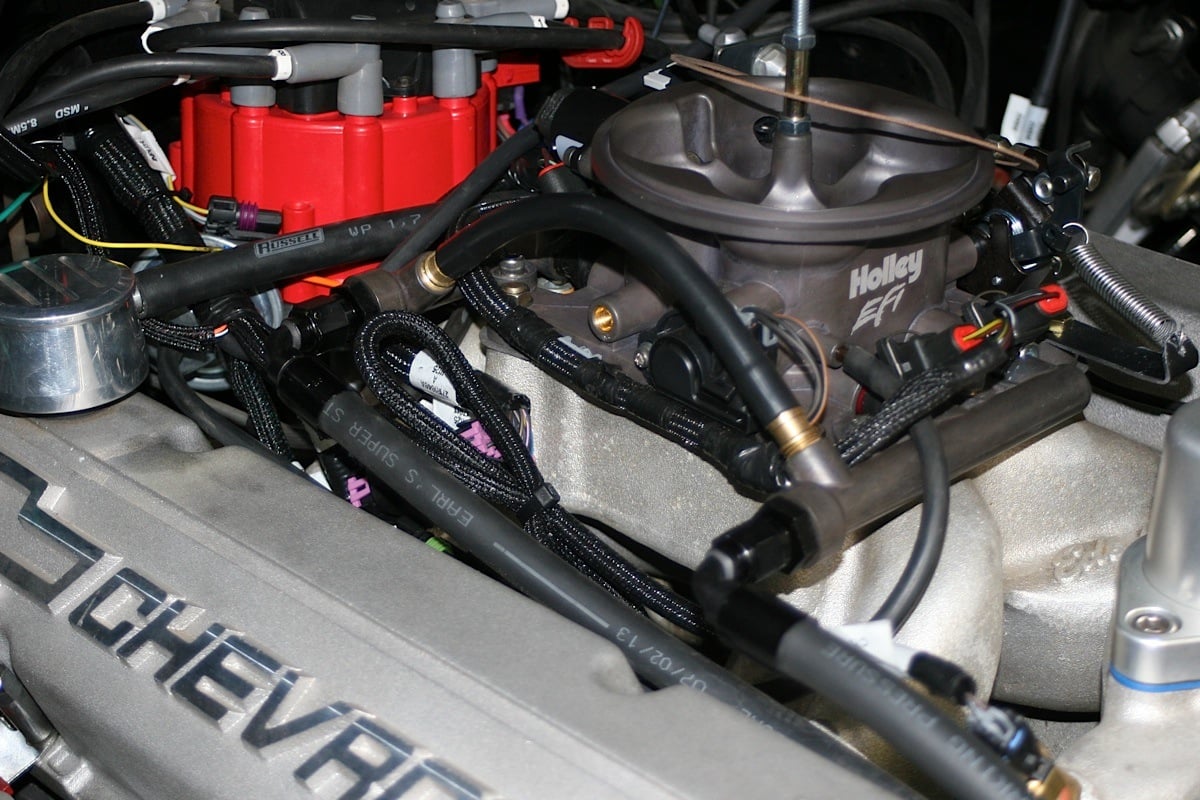
Fuel lines and the main ECU wiring harness were hooked up to the Holley Terminator EFI TBI.
There are also several loose wires in the main wiring harness that must be connected as follows on all systems. These wires come out of the harness about 40 inches from the ECU connectors, except for the “12V Switched” wire. The 12V Switched is about 7 inches from the ECU connecter and is red and white. It needs to be connected to a clean positive 12-volt power source that should only be active when the ignition is on. Check to make sure this source has power when the engine is cranking, as well.
The 12V battery wire is all red and should be connected directly to the battery. The fuel pump and fuel injectors are powered by this wire, and it’s protected by a fuse in a sealed fuse holder. The fuse holder with a 20A fuse is located about 18 inches from the ECU connector.
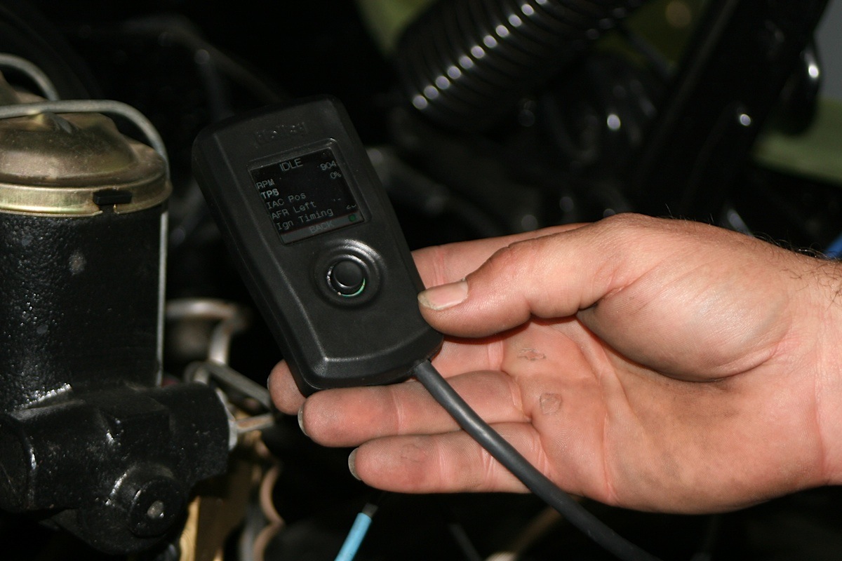
This hand-held controller included in the kit is the interface used throughout the set up and self-tuning process of Holley’s Terminator EFI system.
A green 12V fuel pump wire powers a fuel pump. Don’t use this to power fuel pumps requiring more than 15 amps. For higher current pumps, use this wire to trigger a separate relay and use larger gauge wire to power the pump (10 gauge is recommended). The pump included with the Terminator kit can be powered directly by this green 12V wire, but also requires a ground wire connected to a solid chassis/frame ground.
The chassis ground wire is black and must be connected to a chassis ground point with excellent connectivity to both engine and battery. This should not be connected at the same location as other grounds.
A coil wire is yellow and is a RPM input wire used for some applications. However, the most important signal for the ECU is the engine speed input. If this is done wrong, poor performance will be the result.
Engine Speed Input
There are four engine-speed options on the Terminator systems. Each one is wired differently and you can permanently damage the ECU if you don’t get it right. So follow the instructions carefully during installation.
The first option is Coil engine speed input. It’s to be used if you have stock type mechanical advance distributor with a stock inductive ignition coil, such as older style points distributor–say on a ’72 Chevy Blazer. The EFI does not control the ignition timing. The distributor initial, mechanical, and vacuum advance does, just like it did with the carburetor setup.
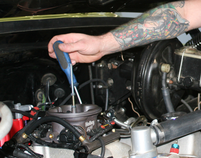
Some adjustments to the throttle body or its linkages may be needed during the initial set up process.
Your second option is Tach Out engine speed input, That’s for use with an aftermarket Capacitive Discharge (CD) ignition system. These are like those made by MSD, Mallory or others. And you’ll need to connect to the Tach Out connection or wire these systems provide. Again, with this setup the EFI will not control ignition timing of the engine; the distributor still does.
Option three is for the GM Small Cap HEI Computer Controlled Distributor (requires Holley Ignition Adapter No. 558-304). Small- and big-block Chevy engines can use this distributor available on 80s through mid-90s factory GM vehicles. It signals the EFI to control ignition timing.
The Fourth option is Ford TFI Computer Controlled Distributor (requires Holley Ignition Adapter No. 558-305). This distributor was used in Ford vehicles with sequentially injected 5.0- to 5.8-liter engines from ’87-’95.
Additional Outputs
Three optional outputs are also available on the system harness to be used for air conditioning shutdown at WOT, and two electric fan outputs. The Air Conditioning Shutdown output is used to trigger a relay and deactivate the air conditioner at higher throttle positions. Electric fan output 1 and 2 provide a ground to trigger a relay for a cooling fan.

These are some typical examples of screen menus you will see on the hand-held controller during the set up process.
Their outputs are located in the Input/Output connector, a three-pin connector located about 52 inches from the ECU. A mating harness is included with the system. The Blazer was not equipped with A/C, so we did not need any of these.
Handheld Connector
The handheld controller used to create the initial system calibration allows simple tuning changes to be performed. It should be installed so it can be easily used in the passenger compartment, and is plugged into the main wiring harness at a connector marked CAN that is 21 inches from the ECU connector. The handheld doesn’t need to stay plugged in after the vehicle is set up and running properly.
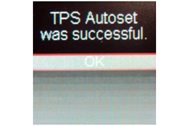
When you see this screen message on the hand-held controller, you are almost ready to begin driving your new EFI-equipped vehicle.
The main battery power and ground connector is on the right side of the ECU. The ground position (black wire) at the bottom (Terminal A), should be wired directly to the battery’s negative post. The upper position (Terminal B) is the positive terminal, and this red wire goes to the positive post on the battery.
For dual-post batteries, it’s recommended that you get separate posts to connect the ECU power and ground to the non-used terminals.
Ready To Rock
With the battery hooked up, the installation was complete. Now the Blazer was ready to start and run. However, before the engine can be fired, the initial power-up, calibration, TPS (Throttle Position Sensor) Autoset, and overall sensor verification must be completed through a simple, but step-by-step process clearly spelled out in the Terminator EFI TBI installation instructions.
A small, but easily read screen on the handheld controller, and a set of buttons and an up-down-right-left selector allow for simple navigation through the menu on the screen. If this process is not followed and performed precisely, you can damage the engine. Fortunately, if you find you have made a mistake during the set up, you have the option to cancel the process and begin again.

We ran the ’72 Blazer on our DynoJet dynamometer during the final phases of set up and self-tuning to keep track of its performance.
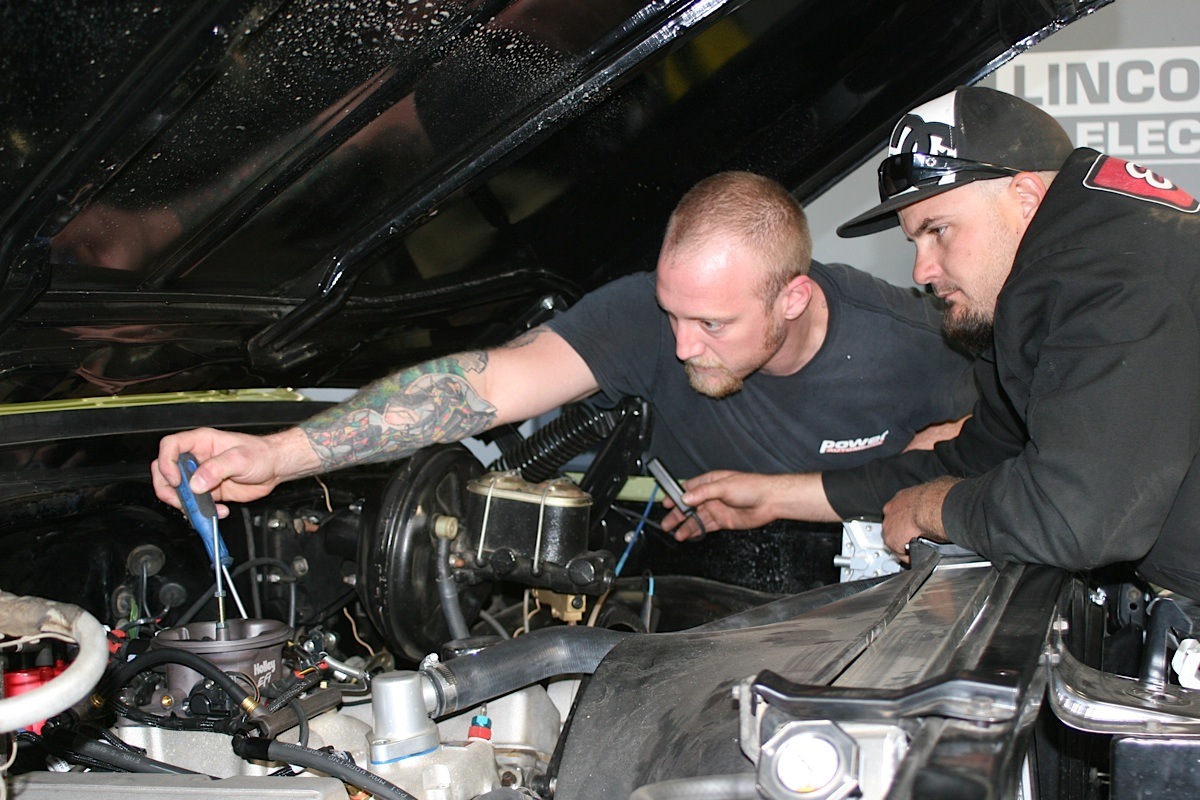
Once the sensor verification is completed, the startup can begin. Using the handheld controller to get to the idle screen and confirm the TPS reading is correct (see Terminator EFI TBI instructions for details), you can crank the engine and begin setting ignition timing. If your vehicle is using a computer-controlled GM HEI distributor, you will have to use a timing light to sync up ignition timing with the ECU.
Smart System
After the engine is running, check for fuel and coolant leaks, and let the vehicle warm up. We had no leaks, and while the Blazer’s 383 was getting toasty, we used the handheld controller’s monitor (per Holley instructions) to check that everything was running properly.
Most importantly, the monitor showed that the Terminator Self Tuning system was in Learn Status, meaning the system would automatically tune itself as we began to drive the Blazer around. This is one of the coolest features of the Terminator EFI TBI system as far as we’re concerned.
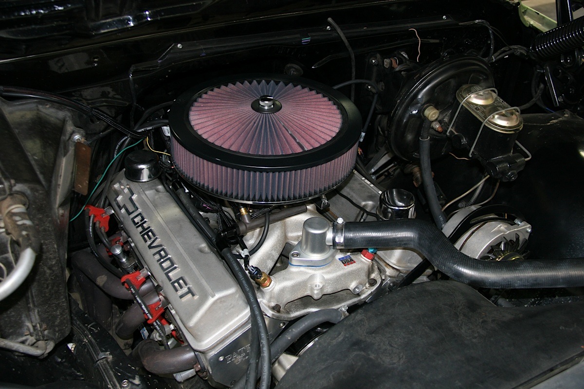
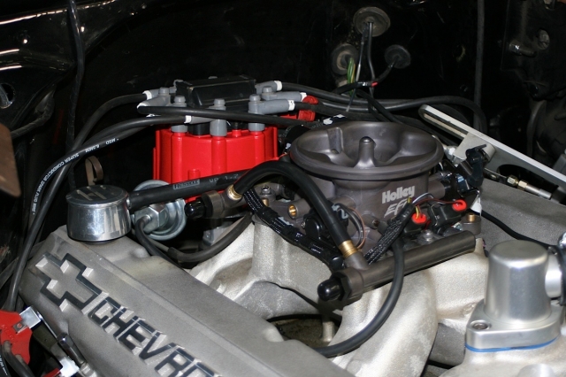
Sitting pretty with a brand new air filter atop it, the Holley EFI 4 BBL TBI fuel-injection system is all buttoned up and is ready to be driven.
And that’s just it. As Burnett put it, “There are thousands of cars and trucks out there, and their owners want nothing more than to be able to drive them to car shows, cruises, and the like. We wanted to make the technology of EFI easily accessible and easy to install.”
As we drove the Blazer for the next couple of days, in a few different situations, the system began performing its self-tuning process. Holley’s installation instructions state that the best way to accomplish this learning process is to drive the vehicle under as many different operating conditions as possible–different engine speeds and loads.
We began by slowly revving the engine in neutral and keeping it steady at different speeds up to about 2500 RPM. This helps the system learn the essential settings. Since the Blazer had an automatic tranny, we also followed the suggestion in the instructions and put it in gear, with a foot on the brake pedal and applied a small amount of throttle.
This system was designed to have you driving your car or truck sooner, as opposed to working on it. – Blane Burnett.
Beyond this basic self-tune, there is a multitude of tuning options you can begin to play with. There is basic tuning and advanced tuning. Basic allows changes in the fuel/air mixture and ignition timing if your vehicle uses a GM HEI unit. Advanced tuning can get you into some fun stuff once you’ve learned the system well and become accustomed to your vehicle’s performance.
With the advanced programming, you can alter coolant enrichment (similar to choke on a carb–it adds fuel as the engine warms up), acceleration enrichment (adds fuel depending upon engine load), RPM activation (for use with extremely large camshafts–typically found in race applications), and many more.
Graduation Day
Wayne began driving Project Iron Blazer again and enjoying the vehicle and its new performance characteristics. Soon it became evident just how much better the truck ran in every situation.
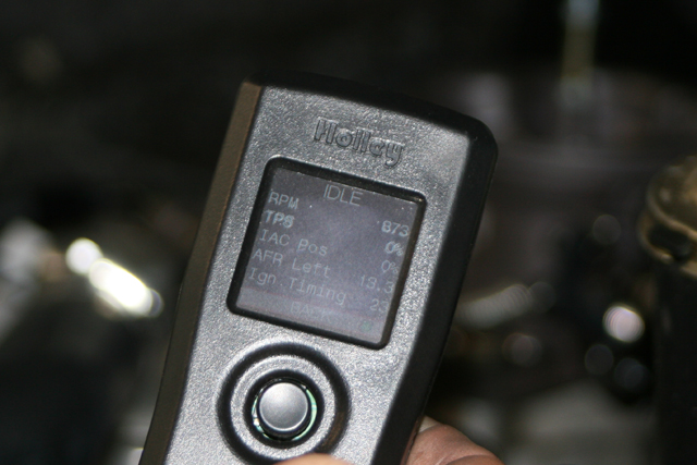
The screen on the Holley hand-held controller shows data such as RPM and degrees of ignition timing during set up and self-tune.
“Driving around town after the tune I was averaging, depending on driving conditions, nearly 12 MPG, whereas before it was running at about 6 to 7 on the carb — that is nearly twice the fuel mileage with the Holley Terminator TBI EFI system.”
“Off-idle acceleration has been greatly improved over the truck’s performance with the carb, the truck really gets up and goes right off the line now, and there’s no stumbling when I stomp on the pedal,” said Wayne. “Throughout the throttle range — all the way to redline — acceleration is smooth and strong, the engine just roars!”
Most importantly, the Blazer’s performance in off-camber situations or on steep hills was remarkably improved with the Holley Terminator system installed. Wayne said, “The truck had often coughed and sputtered when we were carving the dunes or when climbing hills at Glamis, but with the EFI feeding fuel to the engine no matter what the truck is doing, I can drive it anywhere.”
As far as the installation goes, our shop manager Sean Goude said, “The instructions are step-by-step, well illustrated and easy to follow. The great thing is that Holley offers tremendous support, so you can call in for help and send them things like data logs during set up.” He did, however, agree with Holley’s suggestion that, “… the electronic wiring instructions be followed precisely, as any errors here can lead to costly parts failures.
Off-idle, mid-range, full-throttle, climbing or creeping along the side of a hill, Project Iron Blazer is now running like a champ. Goodbye carburetor; hello Holley EFI 4 BBL TBI fuel injection system!


